From this line the remainder of the leader is drawn at an angle dog leg to an arrowhead or dot. Join 7tothe point B.
Draw The Following Lines Used In Projection I Extension Line Ii Leader Line Iii Construction Line न म नल ख त ल इन क ख च Solutions Ed Question Answer Collection
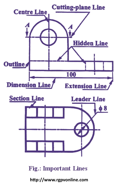
Leader line is the thin solid line used to indicate the feature with which a dimension note or symbol is associated.
. A drawing leader consists of an arrow and a text. A type Continuos Thick. In this way the leader will not be confused with other lines of the drawing.
Draw a line AC at any convenient acute angle with AB. Following are the different types of lines used in engineering drawing. In drawings that do not have cutting planes visible lines will be the thickest lines drawn.
These lines are drawn to make the section evident. They are preferably drawn at a 45 angles. Leader linea thin solid line used to indicate the feature with which a dimension note or symbol is associated- Leader lines are generally a straight line drawn at an angle that is neither horizontal nor vertical Leader lines are.
C The leader is drawn vertical or horizontal or curved. Plus and minus dimensioning is the allowable positive and negative variance from the dimension specified. Paperback with Four color Jacket Cover Pages.
Draw the line firmly with a free and easy wrist-and-arm motion. A type B line thin continuous straight going from the instruction to the feature. End of the extension line.
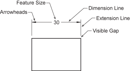
Let the points obtained be l23456 and7. Related Questions on Engineering Drawing. B Dimension lines show the direction and extent of dimension.
A Extension lines are used to indicate the extension of an edge or point to a location outside the part outline. Extension lines begin 15 mm from the object and extend 3 mm from the last dimension line. The thickness of the lines must be chosen according to the type and size of the drawing from any of the six groups given in Table 1.
720 16 33000 About the book CoNteNt The book provides all aspects and detailed study of Engineering Drawing Plane and 1. B One end of the leader terminates either in an arrowhead or a dot. In technical drawings the standards of the leaders and arrows are very important.
Draw a straight line AB. Last Updated on Wed 24 Nov 2021 Engineering Drawing. C type Continuous THIN Freehand.
The first dimension line should be approximately 12 mm 06 in from the object. Engineering Drawing An engineering drawing is a precise technical graphic model that communicates design intent. Leaders should have a uniform and consistent appearance at all drawings independently of the drawing scale.
This line is used to show hidden edges of the main object. ENGINEERING DRAWING PLANE AND SOLID GE O M ETRY By N. Spot the beginning and end points.
Swing the pencil back and forth between the points barely touching the paper until the direction is clearly established. C Leader lines are used to direct an expression in note form to the intended place on the drawing. 170 mm 235 mm Binding.
They are uniformly spaced about 1 mm to 2 mm apart. Draw lines through points 1 2 3. Continuous thin line find its application in engineering drawing as Dimension line Projection line Leader line.
4 5 and 6. Divide a Line into number of equal parts 1. More specifically the arrow size arrow inclination the text size allow line weight etc should all be the same for all leaders in a drawing.
A leader line consists of two parts. Set the divider to a convenient length and mark off seven spaces on AC. Visible lines are drawn as solid thick lines.
A A leader line is a thin continuous line connecting a note or a dimension figure. D Use of common leaders for more than one feature should never be made. A leader line is a line referring to some form of feature that could be a dimension an object or an outline.
It is used by. B type Continuous THIN. Hold the pencil naturally.
For More Engineering Drawing MCQ Click Here. Leader line is drawn may be 30 or 60 to the bottom of dimensions. Tolerance is the amount a particular dimension is allowed to vary.
If the reference is to a line the leader is always terminated at this line with an arrowhead as shown in. 7 Thin chain line find its application as. These are drawn may be vertical or inclined to indicate the height of the dimension figure.
Leader Hatching type lines must be drawn thin and continuous. Leader lines should be inclined between 15 o to 75 o. Vi Leader Lines A leader or a pointer is a thin continuous line connecting a note or a dimension figure with the feature to which it applies.
A leader line is a continuous straight line that extends at an angle from a note a dimension or other reference to a feature An arrowhead touches the feature at that end of the leader At the note end a horizontal bar 6 mm long terminates the leader approximately 3 mm away from mid-height of. Uniform leaders can be easily achieved in modern CAD software using annotative. Leaders are more thin lines used to point to an area of a drawing requiring a note for explanation.
A leader is a thin line used to connect a dimension with a particular area figure 24. What are the types of line in drawing. These are thin continuous lines drawn from a dimension figure to the feature to which it refers.
Consider thin lines are 03 mm and thick lines 06 mm in technical drawing. This line is used to represent the location of a cutting plane. For general engineering drawings the types of lines recommended by the Bureau of Indian Standards shown in table 2 must be used.
Avoid chain dimensioning especially for mechanical objects. This line is used to represent the center line for circles and arcs. The leader line should terminate in an arrowhead or dot.
This line is located in front of cutting planes outlines of adjacent parts censorial Lines and to state center of gravity. One end of the leader terminates either in an arrowhead or a dot. Leader or Pointer Lines.
You can see the general standards that are used generally below. They are generally used as thin lines. But 30 o to 60 o is preferred.
An extension line extends a line on the object to the dimension line. 2015 Reprint ISBN.

Technical Drawing Standards Leader Lines

Extension Lines Drafting Joshua Nava Arts

Engineering Drawing Dimensioning Part 1 Youtube
What Is The Use Of The Continuous Line In Engineering Drawing Quora
Leader Lines Toolnotes
Dimension Appearance And Technique

Technical Drawing Standards Leader Lines

Technical Drawing Standards Leader Lines
0 comments
Post a Comment